How to Reduce Manufacturing Cycle Time, Defects and Waste: 7 Practical Process Improvement Methods

I. Understanding the Three Main Sources of Manufacturing Inefficiency


Manufacturing efficiency is influenced by more than how quickly a machine completes an operation. Production delays, inconsistent quality, excessive material consumption, and poor coordination between processes can all affect a manufacturer’s ability to deliver products on time and maintain consistent performance.

In many manufacturing environments, three common sources of inefficiency deserve particular attention: long cycle times, product defects, and production waste. Although each presents a different challenge, they often share underlying causes, such as unstable process parameters, unsuitable production methods, inadequate planning, or poor workflow coordination. Understanding how these problems develop is the first step toward selecting the right process improvement methods.
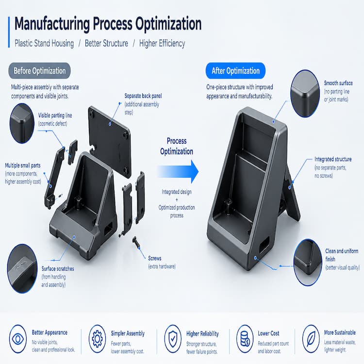
 

How to Reduce Manufacturing Cycle Time, Defects and Waste: 7 Practical Process Improvement Methods


1.1 Manufacturing Cycle Time vs. Production Lead Time

Manufacturing cycle time and production lead time are closely related, but they measure different aspects of production.

  • Manufacturing cycle time is the time required to complete a defined production operation or produce a unit under a specified measurement method. Depending on the context, it may refer to an individual machine operation or the time between completed units on a production line.
  • Production lead time is the total elapsed time required for an order or product to move through the defined production process. It can include processing, waiting, material handling, inspection, and movement between operations.

For example, a CNC-machined component may require 8 minutes of machining time, followed by 3 minutes of deburring and 2 minutes of inspection. However, if the component waits several hours between machining and finishing because of an overloaded workstation, its total production lead time can be much longer than the combined processing time.

This distinction matters because reducing machine cycle time does not necessarily reduce total production lead time. If waiting, setup, material availability, or downstream capacity remains the main constraint, faster machining alone may have little impact on delivery performance.

Effective process improvement therefore requires examining both the time spent performing work and the time products spend waiting to move forward.

1.2 Product Defects, Rework, and Scrap

Quality problems create inefficiency by consuming resources without consistently producing acceptable products.

Manufacturing defects can result from dimensional variation, surface imperfections, material inconsistencies, incorrect assembly, or unstable process conditions. Depending on the defect and product requirements, the affected units may require rework, be downgraded, or be scrapped entirely.

These outcomes have different consequences:

  • Rework requires additional labor, machine capacity, materials, or inspection to bring a product into conformance.
  • Scrap represents material and processing effort that cannot be recovered through normal production.
  • Repeated defects can disrupt production schedules, increase inspection workload, and delay downstream operations.

For example, if a molded plastic component repeatedly falls outside its dimensional tolerance, the problem may involve mold design, material behavior, process parameters, or measurement methods. Increasing inspection frequency may help identify nonconforming parts, but it will not necessarily eliminate the underlying cause.

A more effective approach is to investigate the source of variation, verify the cause with evidence, and implement corrective actions that prevent the defect from recurring.

1.3 Production Waste and Underutilized Resources

Manufacturing waste includes more than discarded materials. It also includes activities and resources that consume time or effort without adding sufficient value to the product.

Common examples include:

  • Excessive waiting between production operations
  • Unnecessary movement of materials and components
  • Repeated setup adjustments or avoidable changeovers
  • Excess inventory and work-in-progress
  • Redundant handling, inspection, or administrative steps
  • Idle equipment caused by material shortages or poor scheduling

Not all waiting, inspection, or inventory is automatically wasteful. Some activities are necessary to protect product quality, maintain process stability, or meet customer and regulatory requirements. The objective is to identify unnecessary effort and delays without compromising these requirements.

For instance, a production line may have sufficient machine capacity but still miss delivery targets because components are not transferred to the next workstation promptly. In this situation, improving material flow and production coordination may be more effective than purchasing additional equipment.

1.4 Why These Three Problems Must Be Evaluated Together

Cycle time, quality, and waste are interconnected. Addressing one in isolation can sometimes shift the problem elsewhere.

Consider a process in which an operator increases machine speed to improve output. If the higher speed creates dimensional instability or surface defects, the apparent productivity gain may be offset by additional inspection, rework, and scrap. Similarly, reducing inventory too aggressively without improving supplier reliability may cause material shortages and production interruptions.

A balanced process improvement approach should therefore consider:

Improvement objective Key question Useful indicators
Reduce cycle time Where is processing or waiting taking too long? Cycle time, throughput, production lead time
Improve quality Why do defects occur, and how often are they repeated? First-pass yield, defect rate, rework rate
Reduce waste Which activities consume unnecessary time, materials, or resources? Scrap rate, material utilization, work-in-progress
Protect delivery performance Are production stages and material supplies properly coordinated? On-time delivery, schedule adherence

The most useful indicators depend on the product, process, and operating environment. They should be defined consistently and reviewed together rather than treated as isolated performance targets.

The key takeaway: Before attempting to speed up production, reduce defects, or eliminate waste, identify where the inefficiency occurs, measure its impact, and investigate its root cause. This provides a reliable basis for selecting the appropriate improvement method—a process explored in the following sections.

II. Method 1 — Map the Production Process and Find Bottlenecks


Before investing in new equipment, increasing labor, or changing production parameters, manufacturers need to understand how work actually moves through the production system. A machine may operate efficiently on its own while the overall production process remains slow because of waiting time, unbalanced workloads, or delays between operations.

Process mapping and bottleneck analysis help identify where time, capacity, and resources are being lost. Rather than improving individual operations based on assumptions, manufacturers can use actual production data to prioritize the changes most likely to improve overall performance.

2.1 Map the Complete Production Workflow

Start by documenting the main production steps, from incoming materials to finished-product inspection and delivery. Depending on the product, the workflow may include material preparation, machining or molding, secondary finishing, component inspection, assembly, packaging, and final quality checks.

For each operation, record several basic details:

  • Processing time: How long does the operation take when work is actively being performed?
  • Waiting time: How long do parts wait before the next operation begins?
  • Setup and changeover time: How much time is required to prepare equipment for a job or switch between products?
  • Output and capacity: How many acceptable units can the operation produce within a defined period?
  • Quality performance: How many units pass the operation without rework or rejection?

These measurements help distinguish time spent adding value from time spent waiting, preparing, moving, or correcting problems. For a straightforward production line, a process flowchart may be sufficient. For more complex workflows, a value stream map can help visualize material movement, information flow, inventory, and delays across multiple operations.

The objective is not to create an elaborate diagram. It is to establish an accurate picture of the current process before deciding what to improve.

2.2 Identify the Production Bottleneck

A bottleneck is an operation or constraint that limits the throughput of the overall production system. It may be a machine with insufficient capacity, a labor-intensive inspection step, a shared tool, a material shortage, or a process with a high defect rate.

Consider a simplified manufacturing line with three sequential operations:

Production operation Available capacity per hour
CNC machining 60 units
Deburring and finishing 40 units
Final inspection 55 units

In this illustrative example, deburring and finishing has the lowest capacity at 40 units per hour. If the operations are dependent and no additional parallel capacity or buffer changes the constraint, the line’s maximum sustained throughput cannot exceed that rate.

Increasing CNC machining capacity from 60 to 75 units per hour would not solve the main constraint. It could simply create more work-in-progress waiting for finishing.

A more effective starting point would be to investigate why finishing is slower. Potential actions might include improving tool access, standardizing manual work, optimizing fixtures, or evaluating whether suitable finishing operations can be combined or performed in parallel without compromising quality.

The example is simplified: real production capacity also depends on downtime, changeovers, yield, product mix, staffing, and scheduling. Bottlenecks can move as these conditions change, so they should be reassessed after significant improvements.

2.3 Look Beyond Processing Time to Find Hidden Delays

The operation with the longest processing time is not always the main cause of excessive lead time. Waiting and coordination delays can account for a substantial share of the total elapsed time.

For example, a custom metal component may require only a short finishing operation, yet wait half a day because the finishing workstation handles several product families. A molded component may be ready for assembly but remain idle until an electronic subassembly arrives from another supplier.

To uncover these issues, examine the entire workflow for:

  • Queues of unfinished parts accumulating before specific operations
  • Frequent machine idle time caused by missing materials, tools, or instructions
  • Repeated movement between distant workstations
  • Delays in inspection, approval, or transfer to the next process
  • Production schedules that create uneven workloads across departments

Tracking work-in-progress and recording the reasons for delays can reveal constraints that are not obvious from machine cycle-time data alone.

Where appropriate, compare processing time with total elapsed time for selected orders or components. A large gap suggests that waiting, transfer, setup, or coordination deserves further investigation.

2.4 Prioritize Improvements Based on Overall Impact

Not every inefficiency deserves immediate attention. The most useful improvement target is usually one that materially restricts throughput, quality, delivery performance, or resource utilization.

A practical prioritization approach is to:

  • Confirm the problem: Use production records and direct observation to verify where delays, defects, or capacity constraints occur.
  • Estimate the impact: Determine how the issue affects output, lead time, quality, and delivery commitments.
  • Investigate the cause: Identify the factors responsible rather than treating the visible symptom as the root cause.
  • Select a targeted action: Choose an improvement that addresses the constraint without creating new problems elsewhere.
  • Measure the result: Compare performance before and after the change using the same measurement method.

For example, if the main constraint is a shared inspection station, possible responses include improving inspection preparation, reducing unnecessary handling, clarifying acceptance criteria, or reviewing whether suitable inspection tasks can be distributed across qualified resources. The right solution depends on the product’s quality requirements and the evidence collected.

The key takeaway: Effective process improvement begins with understanding the complete production flow. Mapping operations, measuring processing and waiting time, and identifying the true bottleneck help manufacturers focus resources where they can make a meaningful difference. Once the main constraints are understood, the next step is to reduce avoidable setup time and changeover delays.

III. Method 2 — Reduce Setup Time and Unnecessary Changeovers


Manufacturing equipment does not produce parts continuously. Time is also required to prepare machines, install tooling, load programs, adjust process parameters, change materials, and verify the first acceptable parts. When these activities take too long, they reduce available production capacity and can delay customer orders.

Reducing setup time is particularly valuable in environments that handle multiple product types, frequent engineering changes, small production batches, or recurring changeovers. The objective is not simply to make operators work faster. It is to make each changeover more predictable, repeatable, and efficient while maintaining product quality.

3.1 Understand Where Setup Time Is Lost

Setup time generally covers the activities needed to prepare equipment for a new production run or product variant. The precise definition varies by manufacturing process and measurement system.

Common setup activities include:

  • Retrieving tools, fixtures, materials, and work instructions
  • Removing the previous tooling or product setup
  • Installing and aligning the next set of tools or fixtures
  • Loading CNC programs or adjusting machine parameters
  • Changing material colors, grades, or product-specific components
  • Producing trial parts and making adjustments
  • Completing first-piece inspection and obtaining the required approval

Some setup activities are unavoidable, but many can be shortened through better preparation and standardization.

For example, if an operator must search for a fixture, confirm the correct program, and wait for inspection support after a changeover begins, the machine may remain idle for reasons unrelated to the technical complexity of the setup itself.

Before making changes, record the duration of individual setup steps. Separating machine downtime from preparation work, adjustment, and approval delays helps reveal where improvement is possible.

3.2 Apply SMED Principles to Shorten Changeovers

Single-Minute Exchange of Die (SMED) is a lean manufacturing method designed to reduce changeover time. Despite its name, the objective is not necessarily to complete every setup in less than ten minutes. The focus is on simplifying the work and reducing the time equipment must remain unavailable.

A practical starting point is to distinguish between two types of setup activity:

  • Internal setup: Activities that require the machine or equipment to be stopped.
  • External setup: Activities that can be completed safely while the equipment is still operating, before the changeover or after production resumes.

Manufacturers can then identify which internal activities can be converted to external activities without creating safety, quality, or operational risks.

For example, in CNC machining, the next job’s tools, fixtures, program, and material can often be prepared before the current batch finishes. The operator can also verify the setup documentation in advance, reducing the number of tasks that must be completed while the machine is idle.

In injection molding, preparation may include confirming the next mold, checking auxiliary equipment, preparing the required material, and ensuring that the approved process documentation is available before the changeover starts.

The exact opportunities depend on the equipment, tooling design, product family, and applicable safety procedures.

3.3 Standardize Tools, Fixtures, and Setup Procedures

Repeatedly rebuilding a setup from scratch introduces unnecessary work and variation. Standardization makes changeovers more consistent and reduces dependence on individual experience.

Useful measures include:

  • Organized tooling: Store tools, fixtures, and accessories in designated locations with clear identification.
  • Standard setup sheets: Document approved machine programs, tooling configurations, fixture positions, and relevant process parameters.
  • Quick-change solutions: Where technically and economically appropriate, use modular fixtures, preset tooling, or quick-clamping systems.
  • Consistent work instructions: Define the setup sequence, critical checks, and acceptance criteria for each product or process.
  • First-piece verification: Establish a clear inspection and approval process so production can resume promptly once requirements are met.

Standardization is particularly useful for repeat orders. Instead of rediscovering the setup requirements each time a product returns to production, the team can reuse verified documentation and proven configurations.

However, setup records should be controlled and updated when engineering changes, tooling modifications, or validated process adjustments occur. An outdated setup sheet can create more problems than it solves.

3.4 Reduce Trial Runs and Repeated Adjustments

After a changeover, equipment may require trial production and adjustments before it produces acceptable parts. Excessive trial runs can consume materials, occupy machine capacity, and delay the start of the production batch.

To reduce these losses, manufacturers should investigate why the initial setup is not consistently producing acceptable output.

Possible improvements include:

  • Verifying tool offsets, fixture alignment, and program revisions before production
  • Using established process parameters from previous approved runs
  • Checking material specifications and preparation requirements
  • Confirming measurement methods and critical acceptance criteria
  • Reviewing recurring first-piece failures to identify their root causes

For processes such as injection molding or silicone molding, stable production also depends on factors such as material condition, mold temperature, pressure, curing or cooling requirements, and equipment performance, as applicable.

The objective is not to eliminate all trial production or adjustment. Certain products and processes legitimately require qualification or first-piece verification. The goal is to minimize avoidable adjustments while retaining the checks necessary to demonstrate conformity.

3.5 Measure the Results of Setup-Time Reduction

A setup improvement should be evaluated using a consistent baseline and measurement method.

For example, suppose a CNC machining operation takes 50 minutes to complete a changeover. After tooling preparation and setup standardization, the average changeover time falls to 40 minutes.

The percentage reduction is calculated as:

Setup-time reduction (%) = (Original setup time − New setup time) ÷ Original setup time × 100%

Using this example:

[\frac{50-40}{50}\times100%=20%]

The changeover time has decreased by 20%.

This does not automatically mean that each part’s machining cycle time has fallen by 20%. Instead, the machine becomes available for production sooner, potentially increasing available capacity and reducing delays between batches.

The practical benefit depends on how frequently changeovers occur, batch size, demand, equipment utilization, and whether the saved time addresses a genuine production constraint. A setup reduction on a non-bottleneck machine may provide limited improvement to total throughput.

Manufacturers should therefore monitor setup time alongside relevant measures such as throughput, first-pass yield, downtime, and delivery performance.

The key takeaway: Reducing setup time requires a structured review of preparation, tooling, changeover procedures, and first-piece approval—not simply asking operators to work faster. By preparing work in advance, standardizing proven setups, and reducing avoidable adjustments, manufacturers can improve production flexibility and make better use of available capacity.

The next step is to address another major source of lost capacity and material: manufacturing defects and the rework they create.

IV. Method 3 — Reduce Defects Through Root-Cause Analysis


Manufacturing defects are a major source of production inefficiency. They consume materials, occupy equipment, require additional labor, and can disrupt delivery schedules. Even when defective parts can be reworked, the additional processing increases production time and reduces the capacity available for new orders.

A reliable way to reduce these losses is to identify why defects occur and implement corrective actions that prevent them from recurring.

The goal of defect reduction is not simply to detect more defective products, but to improve the process so that fewer defects are produced in the first place.

4.1 Identify and Classify Recurring Defects

Before investigating a problem, manufacturers need a clear understanding of what is going wrong, where it occurs, and how frequently it happens.

Depending on the product and process, common manufacturing defects include:

  • Dimensional defects: Components fall outside specified dimensions, tolerances, or geometric requirements.
  • Surface defects: Parts exhibit scratches, burrs, sink marks, flash, discoloration, or other unacceptable surface conditions.
  • Material defects: Components show contamination, inconsistent material properties, incomplete curing, or other material-related problems.
  • Assembly defects: Parts are misaligned, incorrectly fitted, missing, or assembled in the wrong sequence.
  • Functional defects: Products fail to meet specified performance, electrical, mechanical, or operational requirements.

Defect classification helps distinguish different failure modes that may require different corrective actions.

For example, recurring dimensional deviations in CNC-machined components may relate to tool wear, fixture stability, thermal effects, or measurement methods. Surface defects in molded plastic parts may instead involve material condition, mold design, venting, or process parameters.

These are potential causes, not conclusions. The actual cause must be established using evidence from the affected process.

Useful starting data include defect type, frequency, location, production batch, machine or mold, material lot, process conditions, and inspection results. Consistent records make it easier to identify patterns and prioritize investigations.

4.2 Use Pareto Analysis to Prioritize Quality Problems

When several types of defects occur, attempting to solve every problem simultaneously can dilute improvement efforts. Pareto analysis helps identify which defect categories account for the largest share of recorded problems.

The method involves ranking defect categories by frequency, cost, or another relevant measure and calculating their cumulative contribution.

For example, a manufacturer may discover that a small number of recurring defect types account for most recorded rework incidents. Addressing those issues first may produce greater benefits than distributing resources evenly across every defect category.

However, defect frequency is not the only consideration. A rare defect that affects product safety or a critical functional requirement may deserve immediate attention regardless of its contribution to total defect counts.

Prioritization should therefore consider both the overall impact of recurring defects and the severity of individual failures.

4.3 Apply Root-Cause Analysis Tools

Once a priority problem has been identified, structured problem-solving methods can help the team move beyond assumptions.

The 5 Whys

This method involves repeatedly asking why a problem occurred until the investigation reaches a cause that can be verified and addressed. Five questions are not mandatory; the investigation should continue until the evidence supports a useful explanation.

For example:

  • Problem: A machined component repeatedly fails dimensional inspection.
  • Why? The measured dimension varies between production runs.
  • Why? The cutting tool condition differs between runs.
  • Why? Tool replacement is based on operator judgment rather than a defined criterion.
  • Potential corrective action: Establish a documented tool-inspection or replacement method based on actual wear and process capability.

This is only a hypothetical investigation. Tool wear should not be assumed to be the cause without checking measurement reliability, fixture conditions, machine behavior, and other plausible factors.

Fishbone diagrams

A fishbone, or cause-and-effect, diagram organizes possible causes into categories such as people, equipment, materials, methods, measurement, and environment. It is useful when several factors may contribute to the same defect.

Statistical process control (SPC)

Where suitable data and measurement systems are available, SPC can help distinguish routine process variation from unusual changes that warrant investigation. Control charts are especially useful for monitoring processes over time.

SPC does not replace product acceptance criteria or guarantee that every output meets specification. It complements inspection and process analysis by helping teams understand process behavior.

These tools serve different purposes: Pareto analysis helps prioritize problems, fishbone diagrams organize potential causes, the 5 Whys explores causal relationships, and SPC monitors process variation.

4.4 Verify Corrective Actions and Prevent Recurrence

Identifying a plausible cause is only part of the improvement process. Manufacturers must verify that the proposed corrective action actually reduces defects under representative production conditions.

A disciplined approach includes:

  • Establish a baseline: Record the existing defect rate, rework frequency, or first-pass yield using a consistent measurement method.
  • Investigate the cause: Examine process records, inspect affected parts, and test relevant hypotheses.
  • Implement a controlled change: Modify the identified factor while managing other variables where practical.
  • Verify the outcome: Compare results with the baseline and confirm that product requirements continue to be met.
  • Standardize the improvement: Update work instructions, inspection plans, process parameters, or maintenance procedures as appropriate.
  • Monitor continued performance: Check whether the improvement remains effective across subsequent production runs.

For example, if a change to an injection molding parameter reduces a recurring surface defect, the team should also verify dimensional conformity, material performance, and other critical product characteristics. Improving one quality characteristic must not introduce a different failure.

Corrective actions should be proportionate to the risk and complexity of the problem. Significant changes may require additional trials, customer approval, or formal process revalidation, depending on product requirements and applicable quality procedures.

4.5 Measure Quality Improvement With the Right Indicators

Defect reduction should be supported by measurable evidence. Several indicators can help evaluate whether a process improvement is effective.

Indicator What it measures
Defect rate The proportion of inspected units or opportunities identified as defective, using a clearly defined denominator
First-pass yield (FPY) The proportion of units that pass the defined process or production stage without rework
Rework rate The proportion of units requiring additional work to meet requirements
Scrap rate The proportion of units or material discarded because they cannot be economically or technically recovered
Cost of poor quality Costs associated with failures, including relevant scrap, rework, and failure-related expenses

Definitions should remain consistent when comparing performance before and after an improvement. For example, a defect rate based on defective units is not directly interchangeable with a defect rate based on the total number of defect occurrences, because one unit may contain multiple defects.

It is also important to distinguish between detecting more defects and producing more defects. Improved inspection may initially increase the number of recorded defects because previously undetected problems are now being identified. That does not necessarily mean the manufacturing process has deteriorated.

The key takeaway: Sustainable defect reduction depends on reliable data, systematic root-cause analysis, verified corrective actions, and ongoing process control. By preventing recurring quality problems rather than relying on inspection and rework alone, manufacturers can improve first-pass yield, protect production capacity, and reduce avoidable waste.

The next section examines how standardized work and controlled process parameters can help maintain consistent manufacturing performance and reduce unnecessary adjustments.

V. Method 4 — Standardize and Optimize Process Parameters


Manufacturing processes often become inefficient when operating conditions vary between machines, production batches, or operators. Frequent manual adjustments, inconsistent work methods, and undocumented settings can lead to unstable quality, longer cycle times, and repeated troubleshooting.

Process standardization helps reduce this variation by establishing clear work methods, approved operating conditions, and consistent inspection requirements. Process optimization then uses production data and controlled testing to improve performance while maintaining product conformity.

The objective is to establish a repeatable process that consistently meets quality requirements with minimal avoidable adjustment, downtime, and waste.

5.1 Establish Standard Operating Procedures

Standard operating procedures (SOPs) and work instructions define how a manufacturing operation should be performed. Their purpose is to make essential tasks repeatable, reduce avoidable variation, and ensure that critical requirements are understood by everyone involved.

Depending on the process, documented instructions may cover:

  • Equipment preparation, tooling, and fixture installation
  • Material identification, handling, and preparation
  • Approved machine settings and operating ranges
  • Work sequence and handling requirements
  • In-process inspection points and acceptance criteria
  • Responses to abnormal conditions and process deviations

For example, a CNC machining work instruction may identify the approved program revision, tooling configuration, fixture setup, critical dimensions, and required inspection method. A molding process instruction may define material preparation requirements, mold configuration, and the approved operating window for relevant parameters.

The appropriate level of detail depends on the process complexity, product risk, and operator responsibilities. Not every task requires an extensive document, but critical operations should not depend entirely on undocumented individual experience.

Procedures must also remain current. Engineering changes, tooling modifications, and approved process improvements should be reflected in the relevant instructions so that production teams do not unknowingly use outdated methods.

5.2 Optimize Parameters Within a Validated Process Window

Many manufacturing processes depend on several interacting parameters. Operating too far outside a suitable range can increase cycle time, create defects, accelerate tool wear, or compromise product performance.

The relevant parameters vary by manufacturing technology.

Manufacturing process Parameters or conditions to evaluate Potential improvement objective
CNC machining Cutting speed, feed rate, depth of cut, tool condition, coolant application, and fixture stability Improve machining efficiency while maintaining dimensional accuracy and surface quality
Plastic injection molding Melt and mold temperatures, injection speed, pressure, holding time, and cooling conditions Reduce defects and cycle time while maintaining part dimensions and appearance
Silicone molding Material preparation, mold temperature, curing conditions, and relevant pressure or time settings Achieve consistent curing, dimensional stability, and product performance
Assembly Fixture positioning, fastening sequence, torque settings where applicable, and component alignment Reduce assembly errors and improve repeatability

These examples are starting points for investigation, not universal operating recommendations. Appropriate settings depend on material specifications, equipment, tooling, part geometry, and customer requirements.

For instance, increasing CNC cutting speed may reduce machining time, but it can also affect tool life, heat generation, surface finish, and dimensional stability. Similarly, shortening a molding cycle may increase output but could lead to incomplete cooling or curing if the change is unsuitable for the material and part design.

Parameter optimization should therefore consider the combined effect on quality, productivity, equipment reliability, and total production performance.

5.3 Use Controlled Testing to Find Better Operating Conditions

When a process is stable enough to evaluate, controlled testing can help determine whether a proposed change produces a measurable improvement.

A practical approach is to:

  1. Define the objective: Specify the intended improvement, such as reducing machining time, lowering scrap, or improving dimensional consistency.
  2. Establish the baseline: Record current process settings, cycle time, quality results, and other relevant performance measures.
  3. Identify the variables: Select the parameters most likely to influence the outcome.
  4. Test systematically: Change selected variables under controlled conditions and record the results.
  5. Evaluate trade-offs: Check whether improvements in one measure adversely affect quality, tool life, material consumption, or other requirements.
  6. Confirm repeatability: Verify the preferred settings across representative runs, materials, equipment conditions, or production batches as appropriate.
  7. Document the approved process: Update the applicable process records and work instructions.

For complex processes with interacting variables, designed experiments (DOE) may help identify influential factors more efficiently than changing settings through trial and error. For simpler problems, a structured comparison of a small number of controlled trials may be sufficient.

Testing must also respect product and process requirements. Changes affecting critical characteristics, regulated products, or customer-approved processes may require additional qualification, formal approval, or revalidation before routine production.

5.4 Reduce Unnecessary Manual Adjustments

Repeated adjustments during production can indicate that the process is not sufficiently stable, the initial setup is inconsistent, or the control method is inadequate.

Rather than treating every adjustment as an isolated event, manufacturers should record when it occurs, what changed, and whether the adjustment improved the result.

Common opportunities include:

  • Improving tooling condition monitoring and preventive maintenance
  • Verifying fixture alignment and machine setup before production
  • Controlling material preparation and storage conditions
  • Improving measurement methods and inspection consistency
  • Defining appropriate response procedures when process results drift outside expected limits

Where suitable, SPC can help monitor process behavior and identify unusual variation before it leads to widespread defects. However, control charts should be selected and interpreted according to the process and data being measured. They do not replace engineering judgment, product specifications, or required inspection.

The aim is not to eliminate every adjustment. Some processes legitimately require compensation for tool wear or changes in operating conditions. The objective is to make adjustments evidence-based, controlled, and repeatable rather than reactive and undocumented.

5.5 Balance Productivity With Quality and Process Stability

A process should not be considered optimized simply because it produces parts faster. A meaningful improvement must be assessed against the complete set of requirements for the product and operation.

For example, a manufacturer may reduce the cycle time of a molded component by changing its cooling conditions. If the change also increases dimensional variation or causes deformation during handling, the apparent gain may be offset by additional inspection, rework, or scrap.

A balanced evaluation should consider:

  • Productivity: Cycle time, throughput, and equipment utilization
  • Quality: First-pass yield, dimensional conformity, and relevant functional requirements
  • Reliability: Process stability, unplanned downtime, and tool or equipment condition
  • Resource efficiency: Material consumption, energy use where relevant, and avoidable rework
  • Delivery performance: Whether the change improves the overall production schedule rather than shifting delays to another operation

The relative importance of these measures depends on the product and production environment. Critical quality and safety requirements remain constraints, not trade-offs that can be relaxed simply to increase output.

The key takeaway: Process standardization establishes a repeatable starting point, while controlled parameter optimization identifies opportunities to improve efficiency without sacrificing quality. Documenting approved conditions, monitoring process behavior, and verifying changes help manufacturers maintain the benefits over time.

Even a well-controlled operation can experience delays if materials, components, and workstations are poorly coordinated. The next section examines how improving material flow and production coordination can reduce these losses across the complete manufacturing workflow.

VI. Method 5 — Improve Material Flow and Production Coordination


Even when individual manufacturing operations perform well, the overall production process can remain inefficient if materials, components, and information do not arrive where they are needed at the right time.

Unnecessary transportation, excessive work-in-progress, material shortages, and poorly coordinated production schedules can extend lead times without improving product value. These problems are especially common in projects involving multiple manufacturing processes, external suppliers, and final product assembly.

Improving material flow means reducing unnecessary movement and waiting while ensuring that the right materials and components reach each operation when required.

6.1 Reduce Unnecessary Material Movement

Every time a component is moved, stored, retrieved, or transferred between workstations, it consumes time and may introduce additional handling risks.

Poorly arranged production layouts can create long travel distances, repeated transfers, congestion, and delays in locating materials or finished components.

Manufacturers can investigate these problems by mapping material movement throughout the production process and identifying unnecessary transfers.

Practical improvement measures include:

  • Improve workstation layout: Position related operations closer together where practical, considering equipment, safety, and process requirements.
  • Establish designated storage locations: Use clear identification and organized locations for raw materials, tooling, work-in-progress, and finished components.
  • Reduce repeated handling: Review whether components can move directly between appropriate operations without unnecessary intermediate storage.
  • Standardize material identification: Ensure that part numbers, batch information, revisions, and status labels remain clear throughout production.
  • Improve transfer procedures: Define how components are moved, protected, counted, and handed over to the next operation.

For example, a CNC-machined component may require deburring, surface finishing, and inspection before assembly. If each stage is located in a separate area with unclear transfer procedures, the component may spend more time waiting and being handled than receiving actual processing.

A more coordinated layout or transfer system may shorten elapsed production time without changing the machining cycle itself.

Layout changes should still account for equipment access, environmental requirements, contamination prevention, safe material handling, and the need to separate incompatible processes.

6.2 Control Work-in-Progress and Production Queues

Work-in-progress (WIP) refers to products or components that have entered production but have not yet reached the defined finished state.

Some WIP is necessary to accommodate differences in processing time, protect downstream operations from short interruptions, or support stable production. However, excessive WIP can conceal bottlenecks, increase handling, occupy valuable space, and extend production lead time.

When large quantities accumulate between operations, manufacturers should investigate why the downstream process cannot keep pace with incoming work.

Potential actions include:

  • Balancing workloads between connected operations
  • Establishing appropriate WIP limits
  • Improving production scheduling and release decisions
  • Resolving recurring equipment downtime or material shortages
  • Aligning batch sizes with downstream capacity and demand

Pull-based production methods, including Kanban where suitable, can help control the release and replenishment of work according to actual consumption or production needs.

However, reducing WIP indiscriminately can create material shortages or interrupt production if supply and process reliability are insufficient. Appropriate buffer levels depend on demand variability, supplier lead times, process stability, and the consequences of a production interruption.

The objective is not to eliminate all inventory. It is to maintain enough material and work-in-progress to support reliable production without allowing unnecessary queues to grow.

6.3 Coordinate Materials, Suppliers, and Production Schedules

Production efficiency depends on more than internal machine capacity. A missing component, delayed material delivery, unavailable tool, or late engineering approval can interrupt an otherwise well-planned production schedule.

This becomes more significant in custom manufacturing projects that combine different technologies, such as CNC-machined metal parts, injection-molded plastic housings, silicone components, PCBA, cables, and final assembly.

For example, a product may contain several components that can be manufactured in parallel. If assembly begins only after all components arrive, a delay in one long-lead item may hold up the entire product even when the other components are ready.

To improve coordination, manufacturers and project teams should:

  • Identify long-lead materials, tooling, and components early.
  • Align purchasing plans with production requirements and confirmed lead times.
  • Coordinate supplier schedules and communicate potential delays promptly.
  • Confirm that the correct drawings, specifications, and revisions are available before production.
  • Plan inspection, approval, and assembly capacity alongside component manufacturing.
  • Establish clear responsibility for resolving shortages, quality issues, and engineering changes.

Where practical, independent workstreams can proceed in parallel rather than waiting unnecessarily for one another. However, parallel production must be coordinated around interface requirements, approved specifications, and assembly readiness.

Clear communication and realistic scheduling help prevent local delays from becoming project-wide delivery problems.

6.4 Synchronize Production Around the Main Constraint

Material flow and production scheduling should reflect the capacity limitations of the overall system.

If one operation is consistently slower than the others, releasing additional work into the production system may increase WIP without increasing finished output. In such cases, schedules should account for the bottleneck’s capacity and protect it from avoidable interruptions.

Useful measures may include:

  • Ensuring the constrained operation has the necessary materials and tooling
  • Prioritizing jobs according to the production plan and downstream requirements
  • Reducing avoidable changeovers at the constrained workstation
  • Coordinating upstream release rates with downstream capacity
  • Monitoring shortages, downtime, and quality problems that interrupt the constraint

For instance, if final assembly is the limiting stage in a multi-component project, increasing the output of CNC machining or molding may simply create a larger queue of unfinished components. Improving assembly readiness, resolving recurring fitting issues, or coordinating component availability may produce a greater improvement in finished-product throughput.

The most appropriate action depends on the actual constraint. Manufacturers should reassess the workflow after each significant improvement because the limiting operation may change.

6.5 Measure Improvements Across the Complete Workflow

An improvement in one workstation does not necessarily produce an equivalent improvement in total production performance. Manufacturers should therefore evaluate changes using measures that reflect the complete workflow.

Indicator What it helps reveal
Production lead time Total elapsed time through the defined production process
Work-in-progress The quantity of unfinished work accumulating between operations
Throughput The rate at which acceptable finished units are completed
Waiting and transfer time Delays between operations and during material movement
Schedule adherence Whether production stages are completed according to the planned schedule
On-time delivery Whether orders reach the customer by the agreed delivery date

Measurements should use consistent definitions and cover a representative period. For projects involving multiple suppliers, it is also useful to distinguish internal production time from supplier lead time, transport time, and customer approval time.

This makes it easier to determine whether an improvement has genuinely shortened the delivery process or simply transferred the delay to another stage.

The key takeaway: Efficient manufacturing requires coordinated material flow, controlled work-in-progress, reliable supplier communication, and production schedules aligned with actual capacity. Improving these connections can reduce unnecessary waiting and handling, helping the entire manufacturing system perform more effectively.

Once material flow and production coordination are under control, the next opportunity is to improve manufacturability before production scales up—reducing avoidable complexity, rework, and delays at their source.

VII. Method 6 — Improve Manufacturability Before Scaling Production


Not every manufacturing problem can be solved by adjusting machine settings, improving workflows, or adding production capacity. Some inefficiencies originate much earlier, during product development, when design decisions create unnecessary manufacturing complexity or make consistent production difficult.

Features that are difficult to machine, unsuitable wall thicknesses in molded parts, unnecessarily tight tolerances, and poorly designed assembly interfaces can increase processing time, tooling complexity, inspection requirements, and defect risk.

Design for manufacturability (DFM) helps identify and address these issues before they become recurring production problems. Combined with appropriate process selection and production validation, it can support a smoother transition from prototype development to reliable mass production.

7.1 Apply DFM to Identify Manufacturing Risks Early

Design for manufacturability is the practice of evaluating a product design against the capabilities and constraints of the intended manufacturing processes. The goal is to achieve the required function, performance, quality, and appearance while avoiding unnecessary manufacturing difficulty.

A DFM review may examine:

  • Geometry and feature accessibility: Can the required features be produced using practical tooling and process configurations?
  • Tolerances and specifications: Are dimensional and geometric tolerances appropriate for the product’s functional requirements and the selected process?
  • Material selection: Is the material suitable for the required performance and compatible with the proposed manufacturing method?
  • Tooling requirements: Will the design require complex molds, specialized fixtures, additional machining setups, or difficult tool access?
  • Assembly interfaces: Can components be aligned, joined, fastened, and inspected consistently?
  • Quality verification: Can critical product characteristics be measured reliably using suitable inspection methods?

For example, a CNC-machined component with deep, narrow features may require specialized tooling, additional machining operations, or longer cycle times. A design review may identify an opportunity to simplify the geometry while preserving its functional requirements.

Similarly, an injection-molded housing with uneven wall thickness or unsuitable draft angles may present challenges involving filling, cooling, ejection, or dimensional stability. Addressing these issues before mold completion may reduce the need for later tool modifications and process adjustments.

DFM does not mean simplifying every feature regardless of its purpose. Changes must preserve essential product functionality, performance, safety, and customer requirements. Where a design feature is necessary, the objective is to determine how it can be manufactured reliably.

7.2 Select Manufacturing Processes Based on the Complete Requirement

Choosing a manufacturing process based on unit price or production speed alone can create problems later. The appropriate method depends on the relationship between product geometry, material, tolerances, required quality, production volume, tooling investment, and delivery schedule.

Different manufacturing processes offer different advantages and constraints.

Manufacturing process Often suitable for Key considerations
CNC machining Precision metal and plastic components, complex features, and lower-to-medium production volumes Material removal, tool access, fixturing, machining time, and achievable tolerances
Plastic injection molding Repeated production of plastic components, particularly at established volumes Mold design, material behavior, wall thickness, tooling lead time, and process stability
Silicone molding Flexible, elastic, or specialized silicone components Material properties, mold design, curing requirements, and dimensional control
3D printing Prototypes, complex geometries, and selected low-volume applications Material performance, surface finish, dimensional requirements, build time, and production scalability
PCBA and cable assembly Electronic products requiring circuit boards, wiring, and electrical integration Component availability, electrical requirements, assembly controls, and testing
Final product assembly Products combining multiple manufactured and purchased components Interface compatibility, assembly sequence, fastening methods, testing, and traceability requirements

These categories are not interchangeable, and no single process is best for every application. A process that works well for prototype parts may not be the most suitable choice for large-scale production.

For example, CNC machining can support rapid design changes without dedicated injection molds, while injection molding may become attractive when the design is stable and production volume justifies the tooling investment. The actual crossover depends on part geometry, material, tooling cost, cycle time, finishing requirements, and expected demand.

The best decision evaluates the total manufacturing route rather than comparing one operation in isolation.

7.3 Validate the Design and Process Before Mass Production

A successful prototype does not automatically prove that a product can be manufactured consistently at scale.

Prototype production may use different equipment, tooling, materials, or inspection methods from those intended for mass production. Some issues only become apparent when production rates increase, multiple suppliers are involved, or process variation accumulates across larger batches.

A structured transition should therefore verify both product conformity and manufacturing readiness.

Typical activities include:

  • Design and requirement review: Confirm drawings, specifications, critical characteristics, and acceptance criteria.
  • Prototype evaluation: Verify that the product meets its intended functional and dimensional requirements.
  • Manufacturing process review: Confirm that the selected processes, tooling, materials, and equipment are suitable for the intended production conditions.
  • Pilot production or trial run: Produce a representative batch where appropriate to evaluate process behavior, assembly compatibility, yield, and production flow.
  • Quality verification: Inspect relevant characteristics and confirm that the required tests and records are in place.
  • Production readiness review: Resolve significant issues and confirm that responsibilities, work instructions, materials, and production arrangements are ready.

The level of validation should reflect the product’s complexity, risk, industry requirements, and customer expectations. Not every project requires the same formal procedure, but important manufacturing assumptions should be verified before committing to large-scale production.

Where several processes are involved, validation should also consider their interfaces. A molded housing, machined insert, silicone seal, PCBA, and cable assembly may each meet their individual specifications while still presenting fit, connection, or assembly problems when combined.

7.4 Control Design Changes and Preserve Process Consistency

Product development often involves revisions to dimensions, materials, tooling, and assembly details. If these changes are not communicated and controlled, different suppliers or production stages may unknowingly work from conflicting specifications.

This can result in incorrect components, wasted materials, rework, delayed assembly, or disputes over acceptance criteria.

To reduce these risks, manufacturing teams should maintain clear control of:

  • Current drawing and specification revisions
  • Approved materials and component substitutions
  • Tooling modifications and process changes
  • Inspection requirements and acceptance criteria
  • Customer approvals where required
  • The implementation timing of changes across suppliers and production stages

Changes should also be evaluated for their downstream effects. A seemingly minor dimensional revision may affect tooling, fixture design, assembly alignment, inspection methods, or compatibility with existing components.

Effective engineering change control helps ensure that improvements are implemented consistently without introducing new problems elsewhere in the production system.

7.5 Connect DFM With Continuous Process Improvement

DFM is not limited to the initial design review. Feedback from production, inspection, assembly, and customer use can reveal opportunities to improve future revisions and subsequent manufacturing runs.

For example, recurring machining difficulties may indicate that a feature should be reconsidered in the next design revision. Repeated assembly adjustments may reveal an opportunity to improve locating features or component interfaces. Persistent molding defects may justify reviewing the part geometry alongside process conditions.

A practical feedback loop connects manufacturing performance with engineering decisions:

  • Record recurring production problems and their verified causes.
  • Determine whether the issue originates in design, material, tooling, process conditions, or coordination.
  • Evaluate possible design or process changes against product requirements.
  • Validate the proposed change before implementation.
  • Update controlled documentation and monitor subsequent production results.

This approach helps organizations avoid repeatedly solving the same problem through temporary production adjustments when a more fundamental design or process improvement may be available.

The key takeaway: Improving manufacturability before scaling production can reduce avoidable complexity, rework, and manufacturing risk. DFM, appropriate process selection, controlled engineering changes, and proportionate production validation help ensure that a product is not only functional as a prototype but also suitable for consistent, repeatable manufacturing.

Even after a product and its processes are established, manufacturing performance can deteriorate over time as materials, tools, equipment, demand, and operating conditions change. The next section explains how continuous improvement and performance tracking help sustain the gains.

VIII. Establish Continuous Improvement and Performance Tracking


Manufacturing process improvement does not end when a bottleneck is removed, a defect is corrected, or a setup time is reduced. Production conditions continue to change as tools wear, materials vary, equipment ages, product designs evolve, and customer demand shifts.

Without ongoing monitoring, an improvement that initially delivers good results may gradually lose its effectiveness. New inefficiencies can also emerge as changes in one operation affect other parts of the production system.

Continuous improvement provides a structured way to measure performance, test changes, standardize successful solutions, and identify the next opportunity for improvement.

8.1 Establish a Reliable Performance Baseline

Before implementing an improvement, manufacturers need to understand the existing performance of the process. A baseline provides the reference point for determining whether a change has delivered a meaningful benefit.

The indicators selected should reflect the problem being addressed.

Improvement objective Recommended indicators
Reduce production time Cycle time, setup time, production lead time
Increase output Throughput, output per shift, equipment availability
Improve quality First-pass yield, defect rate, rework rate
Reduce material waste Scrap rate, material utilization
Improve delivery reliability Schedule adherence, on-time delivery
Improve overall equipment performance Overall equipment effectiveness (OEE), where appropriate

Each indicator needs a consistent definition, measurement method, and reporting period. For example, cycle time should be measured for the same operation and under comparable production conditions when comparing results.

Manufacturers should also account for relevant differences in product mix, batch size, staffing, equipment, and operating conditions. Otherwise, an apparent improvement may reflect a change in the production workload rather than a better process.

A useful baseline does not need to include every available metric. It should contain enough reliable information to evaluate the specific improvement and identify any unintended consequences.

8.2 Apply the Plan–Do–Check–Act (PDCA) Cycle

The Plan–Do–Check–Act (PDCA) cycle is a practical framework for managing continuous improvement. It helps teams move from identifying a problem to testing a solution and sustaining the results.

Identify the performance gap, establish the baseline, investigate likely causes, and define the intended outcome. Decide how the result will be measured and what quality or safety requirements must remain satisfied.

Implement the proposed change on a controlled scale where practical. Record operating conditions, collect performance data, and ensure that the trial does not compromise product conformity or safe operation.

Compare actual performance with the baseline and intended target. Confirm that the improvement is repeatable and check for adverse effects on quality, equipment reliability, material use, or downstream operations.

If the change works, update the relevant work instructions and process controls, train affected personnel, and monitor continued performance. If the results are insufficient, revise the approach and begin another improvement cycle.

PDCA is iterative rather than linear. A successful change may expose a new bottleneck, while an unsuccessful trial may reveal that the original problem was misunderstood. Both outcomes provide useful information for the next improvement cycle.

8.3 Measure Actual Results, Not Just Intended Benefits

An improvement should be judged by observed performance rather than by the expectation that a new method, tool, or machine will automatically deliver better results.

For example, suppose a manufacturer reduces the average setup time for a production operation from 50 minutes to 40 minutes.

The percentage reduction is:

[\text{Reduction (%)}=\frac{\text{Original}-\text{New}}{\text{Original}}\times100%]
[=\frac{50-40}{50}\times100%=20%]

This represents a 20% reduction in setup time. However, the broader production benefit depends on how frequently the setup occurs, whether the operation is a bottleneck, and how the recovered time is used.

The manufacturer should also verify that the shorter setup has not increased first-piece defects, adjustment time, or unplanned downtime.

For a quality improvement, the same principle applies. A reduction in the recorded defect rate is meaningful only when the measurement method remains consistent and the result is not explained by reduced inspection coverage or a change in product mix.

Where possible, evaluate improvements across multiple representative production runs rather than relying on a single successful trial.

8.4 Standardize Successful Improvements

Once an improvement has been verified, the process should be updated so that the new method becomes part of normal production.

Depending on the change, this may involve:

  • Revising approved work instructions and setup sheets
  • Updating process parameters and inspection plans
  • Modifying tooling maintenance or replacement criteria
  • Training operators and relevant support personnel
  • Updating production planning or material replenishment procedures
  • Recording the change and its approval where required

Standardization reduces the risk that different shifts, operators, or production sites will gradually return to previous working methods.

It is equally important to maintain appropriate change control. If an approved process parameter, tooling configuration, or inspection method is changed later, the impact should be evaluated before the new method is adopted.

For products with critical quality requirements, significant changes may require additional verification or approval before implementation.

8.5 Assign Responsibility and Review Performance Regularly

Continuous improvement works best when responsibilities are clear and performance information reaches the people who can act on it.

Operators may be best positioned to identify unusual machine behavior or recurring handling problems. Process engineers can investigate technical causes and evaluate process changes. Quality teams can analyze defects and verify conformity, while production planners and procurement teams address scheduling and material availability.

Regular reviews should focus on meaningful changes, recurring problems, and corrective actions rather than reporting numbers without decisions.

A practical review might ask:

  • Are cycle time and throughput meeting the intended targets?
  • Have defect and rework levels remained stable after the change?
  • Are bottlenecks appearing in different operations?
  • Have material shortages, tooling issues, or supplier delays increased?
  • Are work instructions and process records still accurate?
  • What is the next improvement opportunity with the greatest operational impact?

The frequency of review should reflect the process, production volume, risk, and speed at which conditions change. Some indicators may need continuous monitoring, while others can be reviewed weekly, monthly, or at defined production milestones.

The key takeaway: Sustainable manufacturing process improvement requires a reliable baseline, controlled testing, objective measurement, and clear responsibility for maintaining the results. By applying PDCA and standardizing verified changes, manufacturers can turn individual improvements into an ongoing system of better quality, more predictable production, and more reliable delivery.

The final section brings these methods together and explains how a capable manufacturing partner can support continuous improvement across the entire product lifecycle.

IX. Applying Process Improvement Across a Custom Manufacturing Project


The seven process improvement methods discussed in this guide can deliver meaningful benefits when applied to individual production operations. However, many custom products involve multiple components, materials, manufacturing technologies, suppliers, and assembly stages. In these projects, overall efficiency depends on how well the complete manufacturing system works together.

A machining operation may meet its cycle-time target, molded components may pass inspection, and electronic assemblies may function correctly, yet the final product can still experience delays because of component incompatibility, incomplete documentation, supplier coordination issues, or assembly difficulties.

Effective manufacturing process optimization requires both efficient individual operations and reliable coordination across the complete production workflow.

9.1 Apply the Seven Methods to a Real Manufacturing Workflow

Consider a custom product that combines CNC-machined metal components, injection-molded plastic housings, silicone parts, a printed circuit board assembly (PCBA), cables, and final product assembly.

Each process has different technical requirements, but all must contribute to the same product specifications and delivery schedule.

The following table illustrates how the seven methods can be applied across such a project.

Process improvement method Example application in a custom manufacturing project
1. Map the workflow and identify bottlenecks Determine whether machining, molding, inspection, component supply, or assembly is limiting overall throughput.
2. Reduce setup and changeover time Prepare CNC tooling and fixtures in advance or standardize recurring production setups.
3. Reduce defects through root-cause analysis Investigate dimensional variation, molding defects, cable connection failures, or assembly nonconformities.
4. Standardize and optimize process parameters Maintain approved machining conditions, molding process windows, assembly instructions, and inspection requirements.
5. Improve material flow and coordination Align component production schedules, incoming inspections, supplier deliveries, and assembly readiness.
6. Improve manufacturability before scaling production Use DFM reviews to identify difficult features, tolerance conflicts, tooling constraints, and assembly risks before mass production.
7. Establish continuous improvement Track production performance, verify corrective actions, update procedures, and monitor results over successive production runs.

The priority should depend on the project’s actual constraints rather than applying every method with equal effort. A project experiencing repeated assembly delays may benefit more from improving component interfaces and supplier coordination than from reducing the cycle time of an already efficient machining operation.

9.2 Evaluate the Complete Manufacturing Process, Not Just Individual Unit Costs

Manufacturing decisions are sometimes made by comparing the quoted price or processing time of individual components. While these factors matter, they do not fully represent the efficiency of the complete production route.

A component with a low unit price may require additional finishing, more demanding inspection, or repeated manual adjustments. A process with a short nominal cycle time may also involve longer tooling preparation, greater scrap risk, or additional downstream work.

A more comprehensive evaluation considers:

  • Manufacturing suitability: Does the selected process match the product geometry, material, tolerances, and expected volume?
  • Quality consistency: Can the process repeatedly meet the specified requirements?
  • Total production time: How do tooling, processing, finishing, inspection, and assembly affect the overall schedule?
  • Coordination requirements: How many suppliers, process transfers, approvals, and component interfaces must be managed?
  • Scalability: Can the process support anticipated demand without creating unacceptable quality or delivery risks?
  • Total manufacturing cost: What are the combined effects of tooling, processing, inspection, scrap, rework, logistics, and assembly?

This broader assessment helps reveal trade-offs that may be overlooked when individual operations are evaluated separately.

It also helps distinguish between an improvement that reduces the cost or time of one operation and one that improves the performance of the complete manufacturing system.

9.3 Choose a Manufacturing Partner That Supports Process Improvement

For custom product development and production, a manufacturing partner can influence efficiency through engineering review, process selection, quality control, production planning, and coordination between manufacturing stages.

When evaluating a potential partner, consider the following capabilities.

  • Engineering and DFM support

Can the team review drawings, specifications, tolerances, materials, and assembly interfaces to identify manufacturing risks before production begins? Can it explain practical alternatives while respecting the product’s functional requirements?

  • Manufacturing process capabilities

Can the partner support the processes required for the product, either directly or through appropriately managed suppliers? Does it understand the constraints and quality requirements of each process?

  • Quality management and process control

Are inspection criteria, process records, corrective actions, and change-control procedures appropriate for the product? Can recurring problems be investigated systematically rather than addressed only through repeated sorting or rework?

  • Production planning and supply coordination

Can the partner coordinate tooling, material procurement, component manufacturing, external suppliers, inspection, and final assembly around a realistic production schedule?

  • Communication and documentation

Are technical questions, drawing revisions, quality issues, and schedule risks communicated clearly and promptly? Are responsibilities and approval requirements established before they become production delays?

  • Continuous improvement

Can the partner use production feedback to identify recurring inefficiencies, implement appropriate changes, and verify whether those changes deliver the intended results?

The right partner is not necessarily the one with the largest number of machines or the shortest quoted processing time. It is the one whose capabilities, controls, communication, and production arrangements match the project’s technical and commercial requirements.

9.4 From Process Optimization to More Reliable Production

Manufacturing process improvement is most effective when it begins early and continues throughout production.

A practical approach is to:

  • Define the product requirements and identify the most important quality, delivery, and performance objectives.
  • Review the design and manufacturing route to identify avoidable complexity and production risks.
  • Establish a realistic baseline for cycle time, yield, lead time, and other relevant indicators.
  • Prioritize the constraints that have the greatest impact on the complete production system.
  • Implement controlled improvements and verify their effects on quality and efficiency.
  • Standardize successful changes and coordinate their implementation across relevant processes and suppliers.
  • Monitor performance and continue improving as product requirements, production volumes, and operating conditions evolve.

This approach avoids treating process optimization as a collection of isolated cost-cutting measures. Instead, it establishes a repeatable method for improving manufacturing performance while protecting product quality and delivery reliability.

How GEMS Supports Custom Manufacturing Projects

At GEMS, we support custom manufacturing projects involving metal, plastic, and silicone components, alongside PCBA, cable assembly, packaging, and product integration services.

Our support includes design for manufacturability (DFM) review, manufacturing process evaluation, production coordination, and the transition from prototypes to repeat production. By considering component requirements, process capabilities, and assembly interfaces together, we help customers evaluate practical manufacturing approaches for their products.

Every project has different requirements, and the appropriate manufacturing solution depends on factors such as product design, materials, tolerances, production volume, quality expectations, and delivery schedule.

Planning a custom product or preparing for mass production? Contact GEMS to discuss your manufacturing requirements, review manufacturability considerations, and explore a suitable path from engineering review to production.

X. Turning Process Improvement into Measurable Results


Reducing manufacturing cycle time, defects, and waste requires more than optimizing individual machines or speeding up isolated operations. It starts with understanding the entire production process, identifying the causes of inefficiency, and making improvements that can be measured and sustained.

The seven methods in this guide provide a practical framework for improving manufacturing performance:

  • Map the production process to identify bottlenecks, waiting time, and capacity constraints.
  • Reduce setup time and unnecessary changeovers through better preparation, standardized procedures, and improved tooling.
  • Address defects at their root causes rather than relying solely on final inspection and rework.
  • Standardize and optimize process parameters to improve consistency and process stability.
  • Improve material flow and production coordination to reduce unnecessary movement, waiting, and work-in-process.
  • Improve manufacturability before scaling production through early DFM reviews, process evaluation, and appropriate validation.
  • Track performance and drive continuous improvement using clear metrics, regular reviews, and controlled changes.

The key is to establish a reliable baseline, prioritize the problems with the greatest operational impact, and verify whether each improvement delivers the intended results. Faster production is only valuable when quality, delivery reliability, and overall manufacturing performance are maintained or improved.

For custom products involving multiple materials and processes, these improvements also depend on how well components, suppliers, production stages, and final assembly work together. A coordinated manufacturing approach can help identify potential problems earlier and support a smoother transition from prototype development to repeat production.

At GEMS, we support custom manufacturing projects involving metal, plastic, and silicone components, PCBA, cable assembly, packaging, and product integration. Through DFM review, manufacturing process evaluation, and production coordination, we help customers assess practical manufacturing approaches for their products.

Planning a custom manufacturing project or preparing for mass production? Contact GEMS to discuss your requirements and explore a suitable path from manufacturability review to production.


How to Reduce Manufacturing Cycle Time, Defects and Waste: 7 Practical Process Improvement Methods

Why GEMS-MFG?

Integrated Factory Resources

We are your one-stop manufacturing solution provider for customized products with the joint effort & support from our 120 partnership subcontractors mainly for the production of metals & plastics. We can expand much faster but the top management decide to keep GEMS a compact, dedicated and professional company, which allows our team to really focus and deliver on your projects without any excuse or compromise. We strive to be a long-term, reliable and trustworthy partner of our customers rather than just being a contractor, and look forward to growing the company with customers’ success.

Manufacturing Veteran Team

With the passing years, we are proud to build up a manufacturing veteran team with rich experience and full expertise to fulfill your specific demand. From mold making, injection molding, die casting, stamping and sheet metal, to 2nd processes like CNC machining, oil spraying, powder coating and chrome plating, and then assembling and packaging and related, we always have someone in house to be an expert to resolve the issues in different stages of product development. We also specialize in providing charger, cable and hub, plus other electronic accessories that support a complete set of product.

Strong Project Management

“Think global, execute local” is the principle of our work. Time, quality and cost are the three key elements to be considered throughout the product development from concept design to mass production. A detailed plan with weekly conference call update is a critical gateway to ensure these three key elements are successfully implemented, also assuring that all parties are on the same page. Communication is the Secret to Success . Everyone works independently to take care his own job, but together we are a team to get things done and are your daily eyes and ears onsite in China.

Flexible Operation & Customization

We offer a wide variety of products, such as mold, component and assembly product, and certain value-added services. For logo or branding product, we have in house resources to complete a color mix that can perfectly match a brand’s unique colors in fast and cost-effective way. Understood the client needs production parts but having a hard time to find a vendor since the order quantity is as low as 1000 or lower. GEMS is well set up for low volume injection molding or die casting projects. Surely our team is also capable of building SPI Class 101 mold that is designed & made for 1 million cycles or more of producing the same high quality parts consistently.