III. How CNC Machining Works
CNC machining transforms a digital design into a physical part through a series of highly controlled and automated steps. This process involves both software and hardware elements, working in harmony to deliver precision-cut components from raw material blocks.
Here’s a breakdown of how CNC machining works from concept to final product:
Step 1: CAD Model Creation
The process begins with a CAD (Computer-Aided Design) file — a 3D digital model of the part. This model defines all dimensions, geometries, and critical features. It serves as the blueprint for manufacturing and must be designed with machining capabilities in mind (Design for Manufacturability, or DFM).
Step 2: CAM Programming and Toolpath Generation
The CAD file is imported into a CAM (Computer-Aided Manufacturing) software, which converts the design into a set of machining instructions. These include:
- Toolpaths: The exact movement of cutting tools
- Cutting strategies: Roughing, semi-finishing, and finishing passes
- Tool changes and spindle speeds: Optimized based on material and geometry
The CAM software generates G-code and M-code, which tell the CNC machine how to move, what speed to use, when to switch tools, and how deep to cut.
Step 3: Machine Setup and Workholding
A machinist prepares the CNC machine by:
- Installing and calibrating tools (end mills, drills, inserts, etc.)
- Securing the workpiece using vises, clamps, or custom fixtures
- Loading the G-code program into the machine controller
Proper setup is critical to ensure accuracy, alignment, and repeatability throughout the machining process.
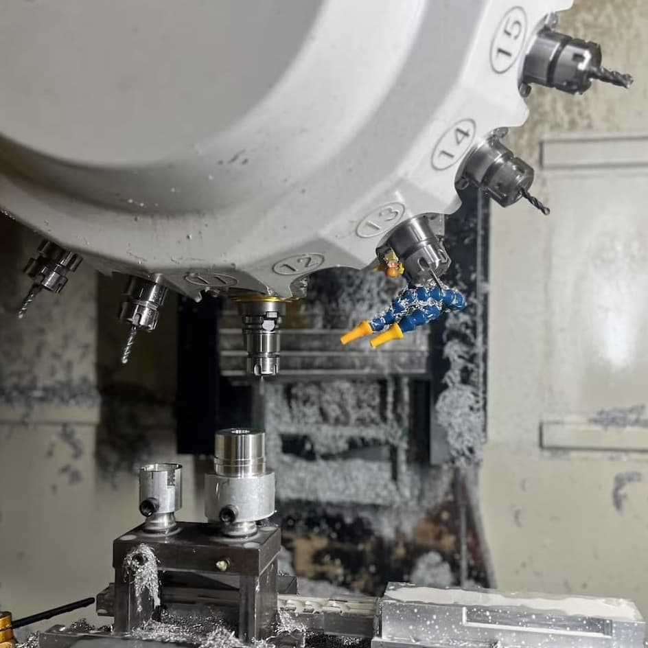
Step 4: Machining Execution
Once setup is complete, the CNC machine begins executing the program:
- The cutting tools remove material from the block along the specified toolpaths
- Sensors monitor spindle speed, temperature, and position to maintain precision
- Multi-axis machines (3-, 4-, 5-axis) allow for complex movements and part geometries
Modern CNC machines often include coolant delivery systems, chip evacuation, and automatic tool changers, streamlining operations for efficiency and quality.
Step 5: In-Process Inspection and Adjustment
For tight-tolerance components, in-process measurements using touch probes or manual gauges help verify dimensions mid-run. Adjustments can be made to compensate for tool wear, thermal expansion, or minor variations in setup.
Step 6: Part Removal and Post-Processing
Once machining is complete:
- The part is removed and cleaned
- Sharp edges may be deburred
- If required, it proceeds to post-machining operations such as surface finishing, heat treatment, or quality inspection